Research Highlights
Determining the strongest carbon nanotube structure: a step on the path to the realization of a light and strong material for the future.
As part of the JST Strategic Basic Research Programs, the research group of ERATO Itami Molecular Nanocarbon Project Research Supervisor Kenichiro Itami (Director and Professor, Nagoya University Institute of Transformative Bio-Molecules (WPI-ITbM)), Group Leader Yuhei Miyauchi (Associate Professor, Kyoto University) and Professor Takahiro Namazu (Aichi Institute of Technology), have identified which out of the many carbon nanotube structures is the most resistant to tensile stress.
Durable and light, carbon nanotubes are predicted to be the important structural materials of the future, even in projects such as space elevators. However, the tensile strength of existing carbon nanotubes has varied greatly from sample to sample. This research is the first in the world to have succeeded in directly measuring the tensile strength of single-wall carbon nanotubes with a determined geometric structure. It was found that small-diameter 'near-armchair' structure nanotubes had the greatest tensile strength.
In addition to adding to the basic scientific consciousness by being the first to determine the key factor which decides tensile strength in carbon nanotubes, the results of this research provide a clear indicator for the eventual realization of carbon nanotubes as a strong and lightweight structural material.
This research was published in the online edition of British scientific journal Nature Communications on July 10, 2019.
About the research:
Mankind has never stopped searching for lighter and more durable materials to make larger structures and more efficient methods of transport. Carbon nanotubes, discovered in 1991 by Professor Sumio Iijima of Meijo University, are anticipated to be one of these (Figure 1a, inset). Carbon nanotubes are tube-shaped structures made from nothing but carbon atoms, with a diameter of one to tens of nanometers and length varying from a few micrometers to a few millimeters. As the light carbon atoms form a network of honeycomb-shaped bonds, nanotubes' strength per unit of mass (specific strength) is extremely high (Figure 1a), and they have garnered attention as the theoretical building material for an elevator to connect the earth and space.
Put simply, carbon nanotubes have infinitely variable structures based on their diameter and the arrangement of their carbon atoms. A carbon nanotube consisting of one single layer is known as a 'single-wall' carbon nanotube, and the layout of that carbon (the nanotube's geometric structure) is determined by its diameter and chiral angle (Figure 1b). Furthermore, and variety of carbon nanotube structures are possible, including single-wall carbon nanotubes nesting to form multiple-wall carbon nanotubes (Figure 1b).
When measuring an individual carbon nanotube, determining its structure and individual characteristics is made very difficult by its tiny size. Although many groups, both in Japan and abroad, have attempted to measure the tensile strength of both single- and multiple-wall carbon nanotubes, they did not implement a system to determine the structure of these nanotubes before taking their measurements. Additionally, it is also known that when measured individually, the tensile strength of a large number of nanotubes did not reach its theoretical potential, and that even when produced using the same method, there was a pronounced variation in the measured values.
In order to make practical use of carbon nanotubes as a material, they need to be bundled and made into ropes. In this case, if the individual nanotubes are of greatly varying strength, a number of weak nanotubes will inevitably be included in the ropes. If this is the case, these points in the rope are a potential site for fractures, meaning that this variation in strength represents a serious problem. However, without knowing if the variation in the carbon nanotubes' strength was due to their structural differences, defects unintentionally introduced during synthesis, or even sample variation among nanotube types, they had no indication of how it could be controlled. Therefore, there was a need to fill the knowledge gap by systematically measuring the tensile strength of single-wall carbon nanotubes with a properly understood structure at the most basic level.
In order to actually measure the tensile strength of a single single-wall carbon nanotube (from hereon in referred to simply as a 'carbon nanotube') with a determined structure, the research team gathered experts with a variety of different academic backgrounds - physics, chemistry and mechanical engineering. By precisely planning a series of experiments, from determining of the structures and synthesis all the way to tensile strength testing, they succeeded in being the first in the world to measure the tensile strength of a carbon nanotube with a determined geometric structure.
First, the carbon nanotubes were synthesized over prepared gaps in a substrate in a process known as alcohol chemical vapor deposition (Figure 2a). Then, using broadband Rayleigh scattering spectroscopy, the geometric structure of the individual carbon nanotubes was determined (Figure 2b). Having determined the structure, under observation by scanning electron microscope, they used a tiny supporting tool called a microfork to pick up the carbon nanotubes and install them in a MEMS device for tensile strength measurement. This MEMS device is composed of two stages, with a force-measuring spring in the stage on the left of Figure 2d (the following stage). When the right-hand stage (the driving stage) is moved in the direction of the arrow in Figure 2e, force is applied to the single-wall carbon nanotube along its axis and the following stage is simultaneously pulled in the direction of the arrow. The driving stage continues to move until the carbon nanotube breaks. By using the distance travelled by the following stage up to the point where the carbon nanotube broke, alongside Hooke's Law, they were able to determine the tensile strength of the carbon nanotube.
The research group eventually succeeded in measuring the tensile strength of carbon nanotubes with 16 different geometric structures. Each carbon nanotube's tensile strength was different (Figure 3a), and out of the 16 measured carbon nanotubes, the 'near-armchair' structured, small diameter carbon nanotube with a chiral angle of around 30 degrees was found to have the highest tensile strength (Figure 3b, 3c). In this experiment, the strength of a small diameter carbon nanotube with near-armchair structure was around 1.5-2 times greater than a carbon nanotube with a comparatively large diameter non-armchair structure.
The research group, considering these two causes: the angle at which the carbon-carbon bonds and the direction of the tensile stress intersects (this being the same as the chiral angle), and the buildup of stress at the ends of the defects that are thought to almost certainly exist in carbon nanotubes synthesized using current methods (see Figures 4a and 4b), were able to find a way to organize the seemingly variable degrees of tensile strength, and furthermore to produce a relative equation for the measurement of tensile strength (Figure 4b). The relationship between the chiral angle and the variation in tensile strength reflects the difference in force upon each carbon-carbon bond that is determined by the nanotube's structure. This research provides the basis for solving these problems one by one.
Figures
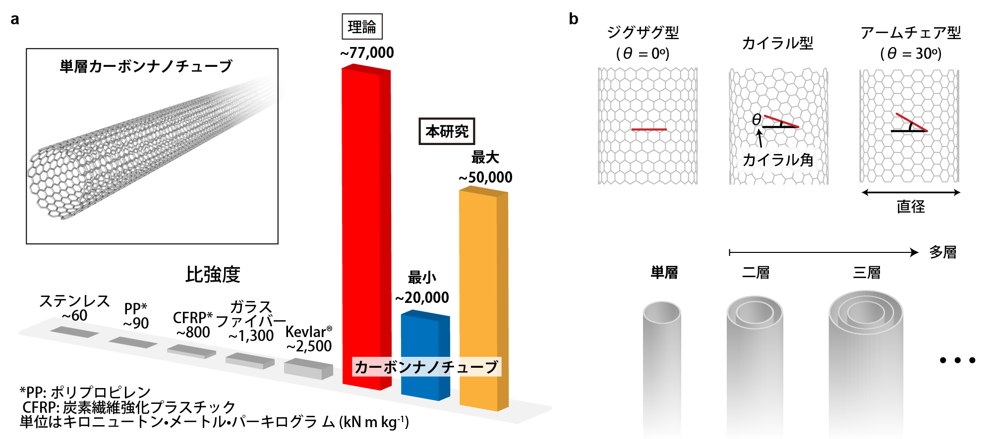
Figure 1: Comparison of strength of carbon nanotubes vs other representative materials
a) The theoretical strength of carbon nanotubes is shown alongside the highest and lowest values found in this study. The inset image shows a single-wall carbon nanotube.
b) Classification of carbon nanotubes. Carbon nanotubes are classified according to their diameter and chiral angle (above). When single-wall carbon nanotubes are nested they form multiple-wall carbon nanotubes (below).
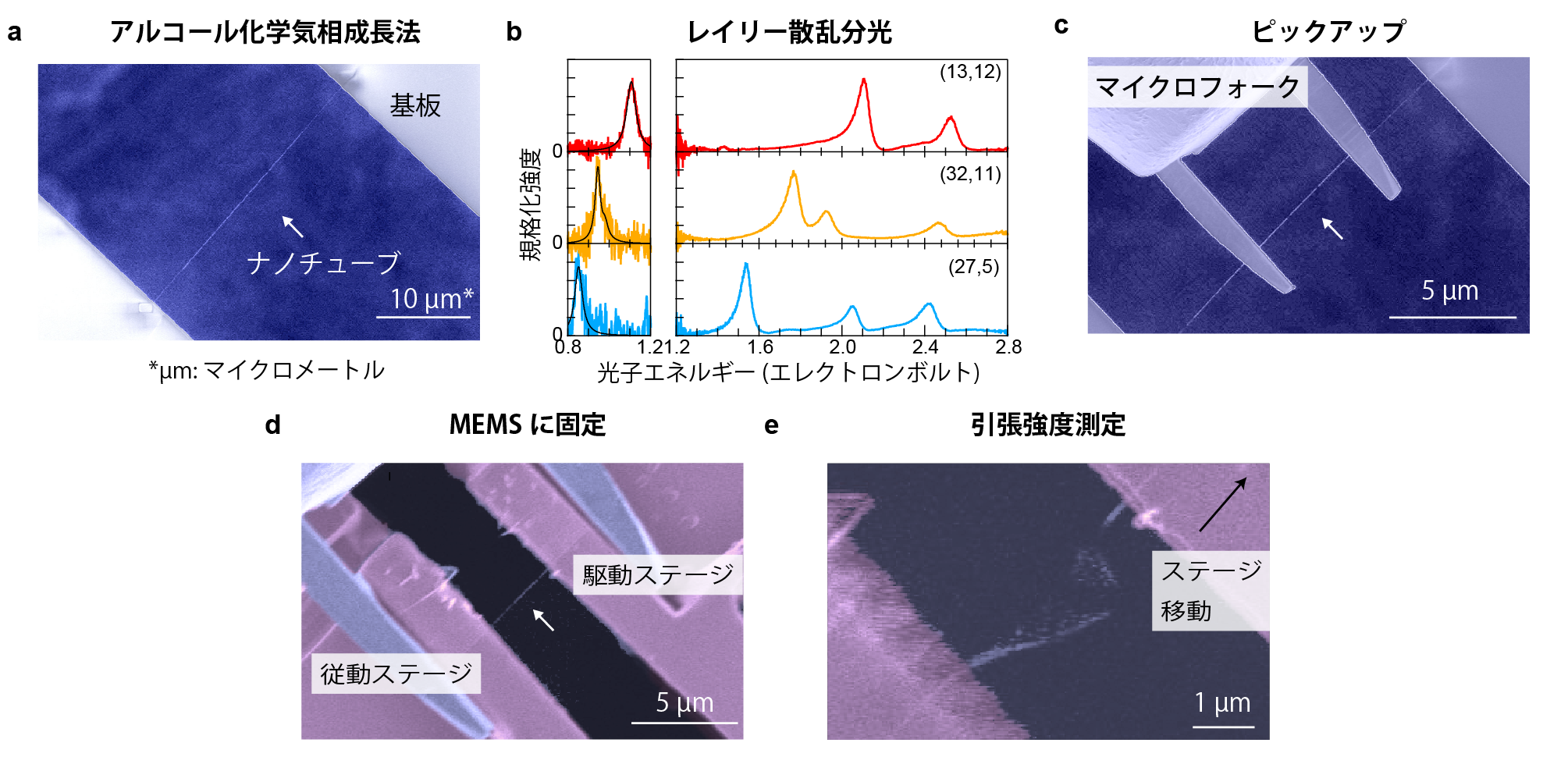
Figure 2: Measuring the tensile strength of carbon nanotubes with a determined geometric structure
a) Observation of a carbon nanotube using a scanning electron microscope. The carbon nanotube is positioned across a prepared gap in the substrate.
b) Broadband Rayleigh scattering spectroscopy of three structurally different carbon nanotubes. The peak photon energy differs with each different structure, and using related information from previous studies, it was possible to determine the carbon nanotubes' structures.
c) The carbon nanotube is picked up using a microfork
d) Having been picked up, the nanotube is placed across the two stages of the MEMS device
e) The nanotube is broken and the tensile strength is determined
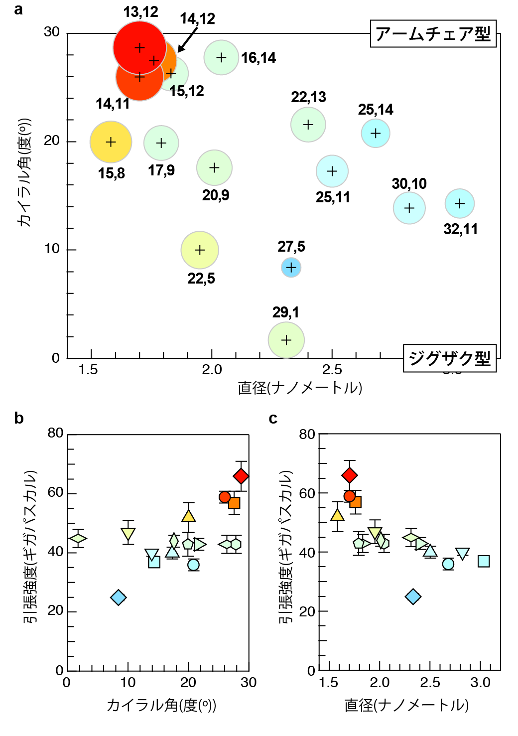
Figure 3: The relationship between tensile strength and geometric structure
a) Tensile strength is represented by the diameter of the circles, where greater diameter = greater tensile strength. The coordinates representing the center of each circle correspond to a carbon nanotube's diameter and chiral angle. Beside each circle is written the chiral index, which is worked out individually for each nanotube from its diameter and chiral angle. In this study, the carbon nanotube with the greatest tensile strength (66 gigapascals) had a near-armchair structure, a small diameter of 1.70 nanometers and a chiral angle of 28.7 degrees, with a chiral index of 13,12.
b) Relationship between chiral angle and tensile strength
c) Relationship between diameter and tensile strength
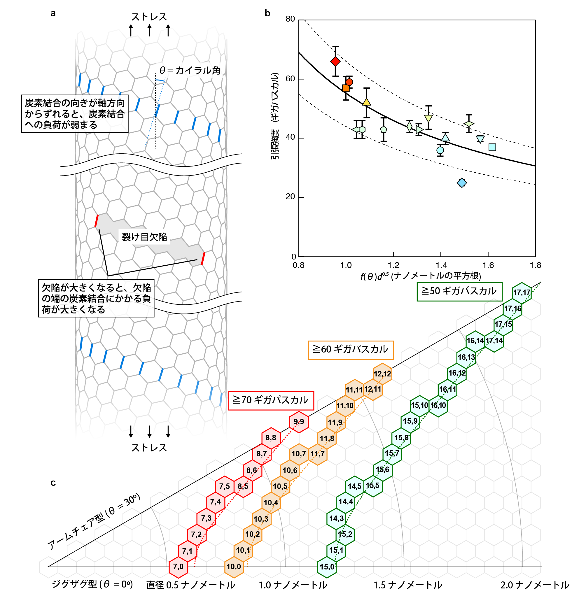
Figure 4: Understanding the relationship between structure and tensile strength
a) When a carbon nanotube is pulled along its axis, the greatest stress is placed upon the carbon-carbon bonds highlighted in blue. As the difference between the orientation of these bonds and that of the carbon nanotube itself increases (i.e. as it gets closer to the armchair structure), the stress on each of the bonds decreases and the nanotube becomes able to resist stronger pulling forces. As no carbon nanotube in this study had the theoretically possible tensile strength of over 100 gigapascals, it is though that there was more than one crack-like defect in each tube. Although the exact nature of these defects has not been identified, theoretically, no matter the nature of the defect, force is concentrated at the carbon-carbon bonds at its ends (highlighted in red), and this becomes the failure point. The further around the circumference of the nanotube the defect reaches, the greater the stress on the red carbon-carbon bonds becomes, and with it the lower the tensile strength of the carbon nanotube.
b) Factor ( f (θ) d5 ) expressed as a function, based on the measured value of tensile strength in (a). The tensile strength is inversely proportional to the factor f (θ) calculated from the chiral angle and the square root of the diameter d of the nanotubes. The graph shows the dependency of f (θ), where even if nanotubes are stressed with the same force, the force exerted on each carbon-carbon bond differs according to the chiral angle. Furthermore, according to linear fracture mechanics, the relation to the square root of the diameter can be explained by the fact that the larger the nanotube's diameter, the longer the faults linked to cracking are able to become.
c) A map of predicted tensile strength based on current single-wall carbon nanotubes. The figures in the honeycomb segments are the chiral indices.
Vocabulary
1) Near-armchair structure
When the carbon atoms are arranged along the carbon nanotube's circumference in a structure that resembles the arms of a chair, this is known as the armchair structure. The near-armchair structure is simply the name for a structure that is very similar.
2) Chiral angle
In Figure 1b, the angle where the honeycomb's zig-zag (the red line) meets the circumference of the nanotube (the black line) is known as the chiral angle.
3) Alcohol Chemical Vapor Deposition
A method of carbon nanotube synthesis involving reacting alcohol gas (the carbon source) with a metal catalyst at high temperature.
4) Broadband Rayleigh scattering spectroscopy
Measuring light scattered by samples smaller than the wavelength of that light is known as Rayleigh scattering spectroscopy. When carbon nanotubes are irradiated with visible to near infrared light, light from particles called excitons is scattered. In most previous research only scattered light with wavelengths below 1000 nanometers had been measured, but measuring only in these wavelengths did not produce satisfactory results in determining geometric structures. In this study, the range of measurement was increased to 1600 nanometers, and this made it possible to determine the structures much more accurately. The research group termed this process broadband Rayleigh scattering spectroscopy.
5) MEMS
Abbreviation of MicroElectrical Mechanical System. A microsystem integrating minute electrical and mechanical parts such as actuators and sensors.
6) Hooke's law
Law for deducing the force applied to a spring by measuring its extension.
Journal Information:
The article "Strength of carbon nanotubes depends on their chemical structures" by
DOI: 10.1038/s41467-019-10959-7
2019-07-10